Service Hotline:400-096-8228

Kunwei Equipment - Bringing Craftsmanship to the Future
Committed to providing you with the most suitable high-performance extruder
This article is from an external website. If there are any errors or omissions, please feel free to correct them.
Operators and factory engineers already know that there are many technologies that can improve the performance of twin screw extruders. However, most of these methods are empirical word-of-mouth and have not appeared in any equipment manuals. They are generally not mentioned in textbooks and technical papers.
But sometimes adjusting a few small details can have a significant impact on the performance of the extruder. These techniques can be divided into three categories: installation techniques, machine maintenance, and program usage. This article will be divided into two parts, introducing ten methods to improve the mixing performance of twin screw.
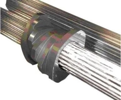
Using insulation gaskets
Most of the feeding section is water-cooled. However, because the barrel is bolted to the flange and then connected to the heated barrel, heat is continuously transferred from the hotter barrel to the colder barrel.
Therefore, barrel 2 is usually unable to maintain a sufficiently high temperature. In typical cases, the operator sets the temperature of barrel 2 to 180 ℃, but due to the heat loss of the feeding barrel, the temperature will never exceed 135 ℃.

Source: Leicester Ritz
The simplest solution is to install an insulation gasket between the flanges of the feed drum and barrel 2. These washers are usually 1mm thick, and we recommend stacking the two washers together for better insulation performance. There will still be some heat conduction through threaded components and screw shafts, but not as much as without insulation.
New extruders typically come with insulators, but many operators do not realize their importance and discard them when disassembling the barrel. After a few years, the insulation gasket should be replaced as the material will degrade and shatter.
Side feeding of powder
Side feeding is widely used to feed fillers into twin screw extruders. Many processors require a very high amount of filler filling, which is usually a low bulk density (fluffy) material. The achievable ultimate load is usually limited by two parameters:
1. Volume capacity of side fillers and main extruder screws.
The volume capacity is based on the free volume of the twin screws of the side feeder and the main extruder screws, as well as the rotational speed of the two screw groups. If the material can be fed into the conveying section by removing the bolt from the side feeder of the extruder, it may be easy to feed the material at a high rate. However, when the filler is connected to the extruder, the capacity is usually limited by the amount of material that the main extruder screw can accept.
Therefore, it is best to combine the main extruder screw with a long pitch (long thread forward) threaded element at the position of the filler, extending from 2D to 4D downstream of the filler. This is to maintain the rapid forward movement of the melt in the extruder to allow the maximum free volume for the filler to enter. If the screw design causes any material downstream of the filler to "block", it will severely limit the amount of filler that can be fed.
2. The exhaust capacity that allows air to escape from the extruder.
The purpose of exhaust is to make it easy for air to escape while preventing a large amount of filler from leaking from the exhaust port. The best configuration is to install a top vent on the barrel immediately upstream of the side filler. Sometimes a small half slot ventilation plug can also be used at the top of the side filler.
Here are some other factors to consider:
Height of feeder drop: Ideally, the feeder should be as close as possible to the top of the side feeding port to minimize the drop. If a fluffy material is allowed to fall from the air, it will inflate to the point where the bulk density significantly decreases. This will limit the throughput of the entire production line.
Feeder Mixing Type: Ensure that the mixer in the filler feeder does not inflate the material and reduce its bulk density. Many feeder manufacturers have specialized powder mixer designs.
Ensure ventilation of the filler hopper: Along with the filler, the filler also introduces a large amount of air into the extruder. The top of the opening on the side filling slot will be responsible for ventilation. If you see a sturdy cover on the chute with a circular short tube and a flexible connector connected to the feeder, having another vent will be very important.
Ground all hoppers/chutes to remove static electricity: Some materials may generate static electricity due to friction. Static charges can cause powder to adhere to the inner surface of the hopper and chute, leading to problems such as agglomeration. A simple solution is to connect the ground wire (recommended to use gauge 10) from the chute to a known good grounding point on the rack.
Compressed air injector: If agglomeration persists, special solutions are sometimes required. A hopper vibrator can be used, but it is difficult to determine size and installation. Another option is a "blaster" with jet nozzles, which are cleverly placed inside the chute wall to break any clumps before they become too large. The air nozzle is connected to the solenoid valve, which is activated by a repeat cycle timer. This allows you to set the injection cycle and the dwell time between injections. It is best to install a small air storage tank upstream of the solenoid valve to provide sharp air pulses.
High pressure water pump
As is well known, turbulence in pipelines can cause greater heat transfer than from the pipe wall and laminar flow. The laminar flow phenomenon occurs at low fluid velocities caused by low-pressure transportation. In the case of laminar flow, a stable boundary layer will be formed, just like the insulator between the main body flow and the pipe wall. The fluid "layer" slides on adjacent layers without mixing or taking away too much heat.
In the turbulence caused by high-pressure transport, there is a high degree of lateral momentum exchange, which destroys the boundary layer. As a result, intense fluid motion leads to much greater heat transfer from the pipe wall to the fluid.
The simplest way to cause turbulence in the cooling hole of the barrel is to increase the conveying pressure. The supply pressure of the extruder cooling recirculation system is usually 20 to 60 psi. To achieve turbulence, a pressure of approximately 120 psi is required. This can be relatively easily achieved by changing the pump in the recirculation system to a high-pressure type. Almost all extruder cooling system components (hoses and valves) have a rated pressure of at least 150psi, so 120psi still has a certain safety factor.
In a highly exothermic process, the advantage will immediately become apparent, usually greatly reducing or even eliminating temperature coverage. Another advantage of turbulence is that it can prevent the cooling holes from scaling due to scaling.
Acid flushing cooling hole
The barrel of a water-cooled extruder is a heat exchanger, and like all other heat exchangers, the coolant holes will scale due to scaling. Most operators have noticed that the cooling performance of the new extruder is much better than that of the extruder after three or four years of operation. This is because the new extruder barrel has smooth, shiny, and newly drilled cooling holes. The hole lining of the old machine has a layer of hard shell mineral deposits that act as an insulator.
If left unchecked, the accumulation of scale can lead to more serious problems. Ultimately, the cooling holes may become completely blocked, resulting in zero water flow. If this situation occurs, the only solution is to remove the barrel from the extruder and drill all cooling holes - this is a time-consuming process.
Therefore, just like using acid to remove scale from household water heaters, the cooling holes can be regularly pickled.
Use synthetic gear oil

The gearbox is the heart of a twin screw extruder. If it is damaged, repairing it can be expensive and may take a considerable amount of time. Everyone can easily do one thing to avoid gearbox problems: switch to synthetic gear oil. Synthetic oil is a huge advancement in lubrication technology:
It is smoother and can reduce friction.
Extend the service life of gears, bearings, and seals.
The transmission operates cooler and quieter.
Synthetic oils do not lose viscosity due to mechanical shear.
It maintains a high viscosity at high temperatures.
It improves the overall efficiency of the gearbox。
9 Guangtai Road, Dujiangyan City, Chengdu City, Sichuan Province
45 Limao Road, Wujin District, Changzhou City, Jiangsu Province
400-096-8228
sales@njkwls.com

Nanjing Kunwei Lansheng Extrusion Intelligent Equipment Co., LTD
Address: No. 9 Guangtai Road, Dujiangyan City, Chengdu City, Sichuan Province
45 Limao Road, Wujin District, Changzhou City, Jiangsu Province
Tel:400-096-8228
E-mail:sales@njkwls.com